 ×
×

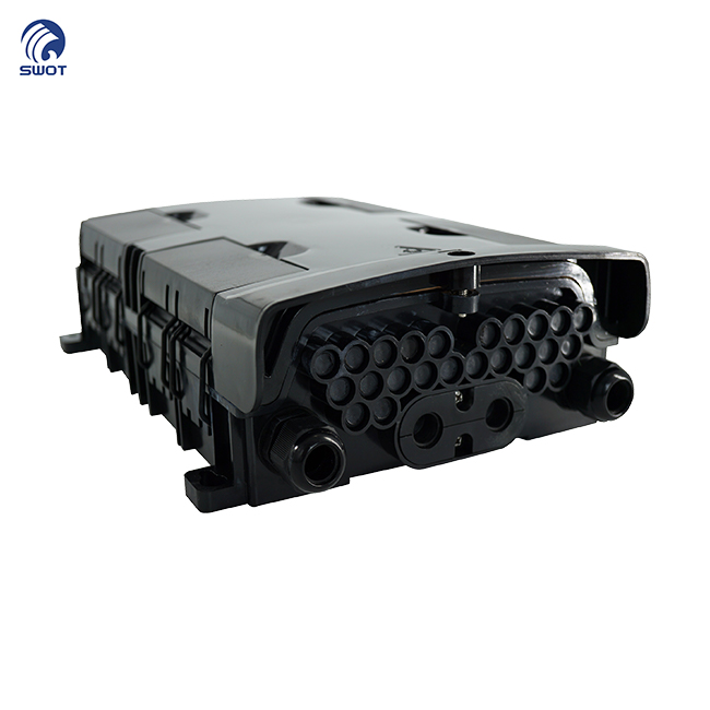
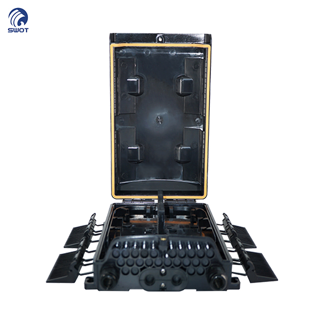
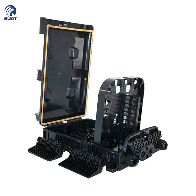
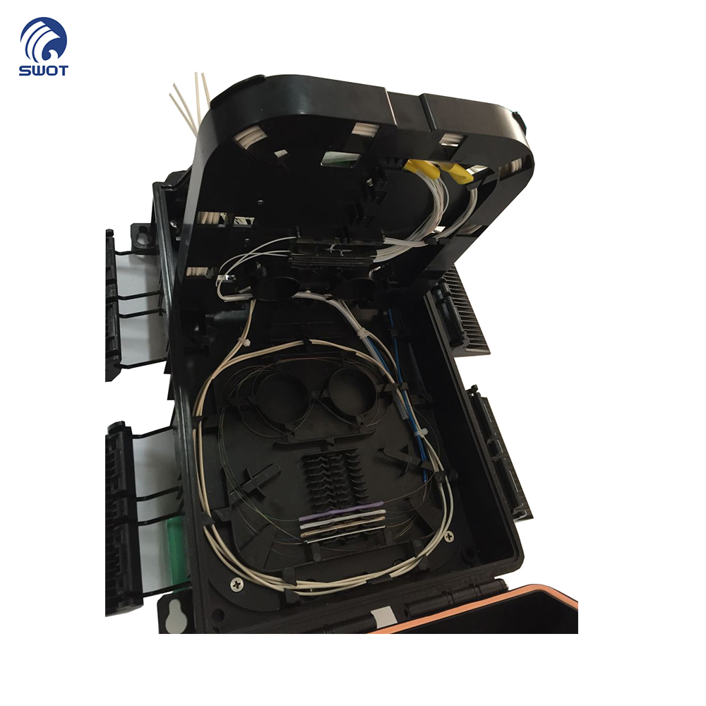
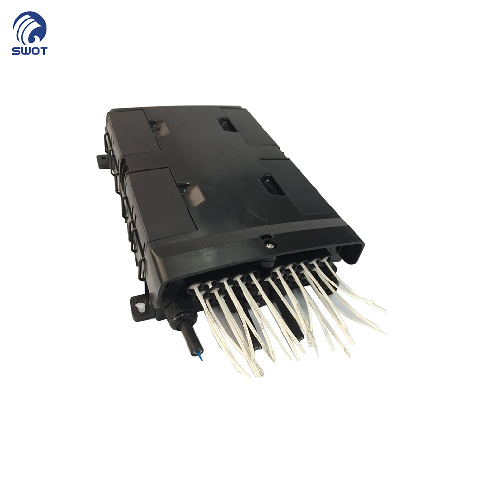
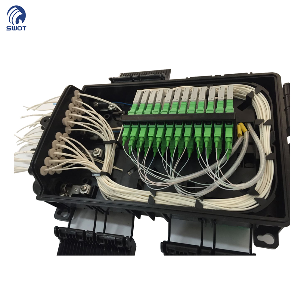
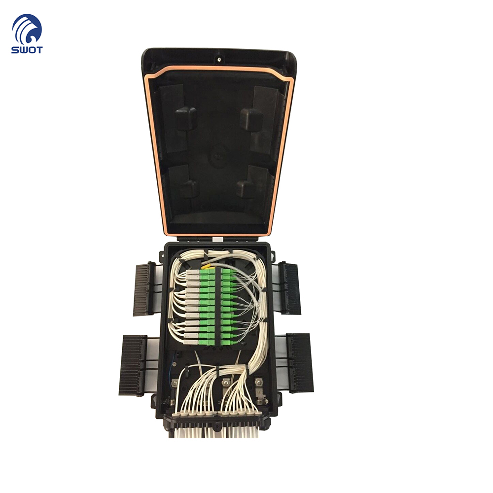
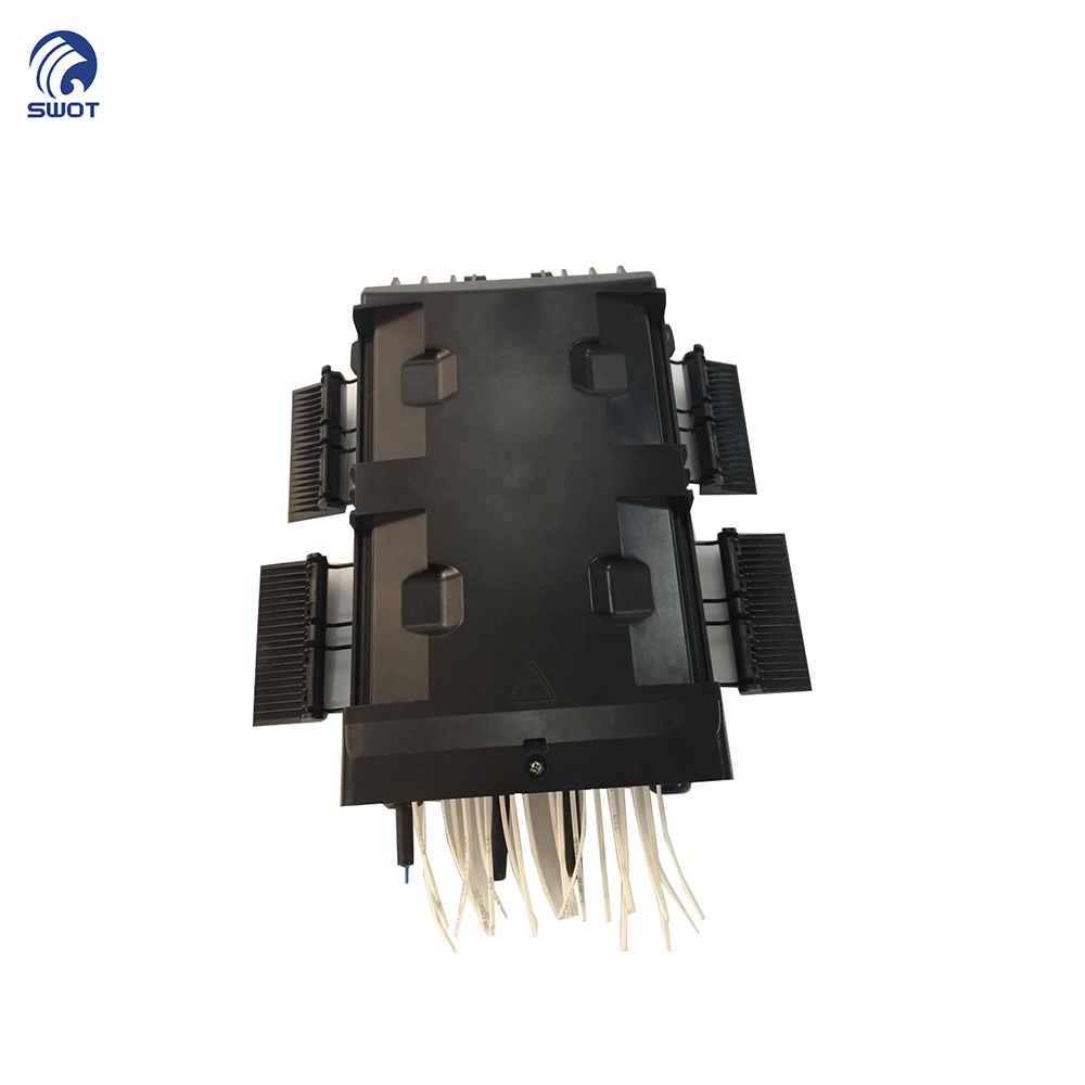
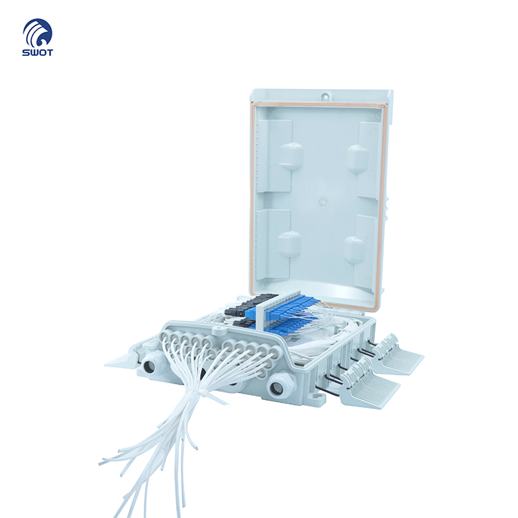
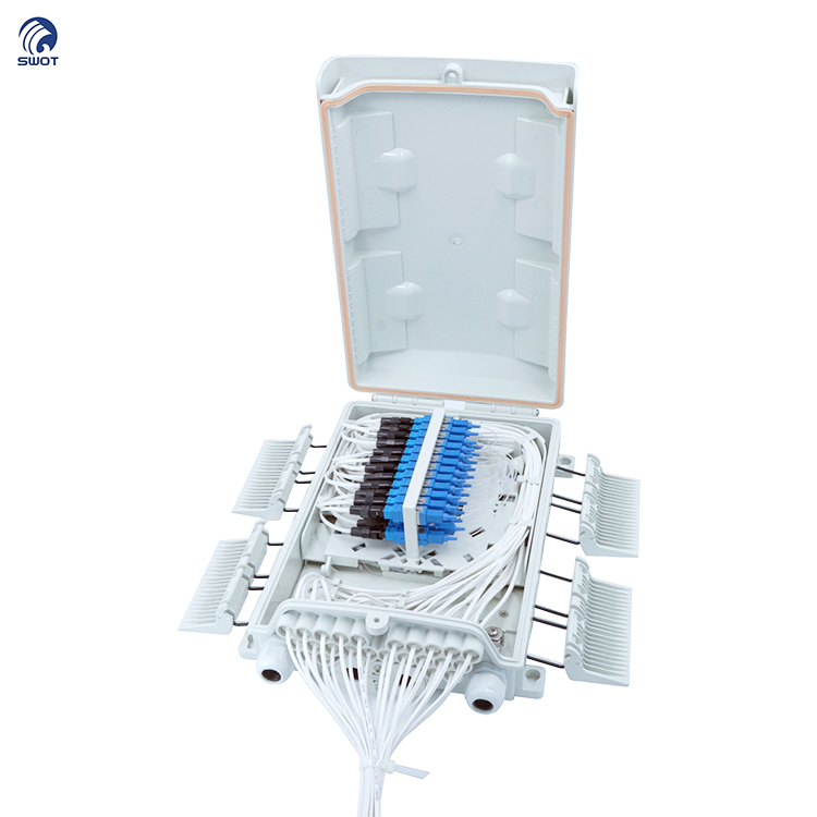
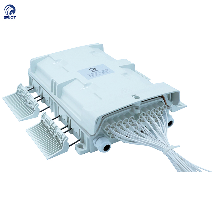
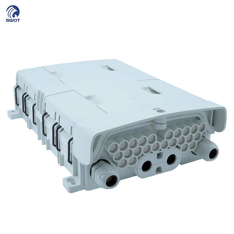
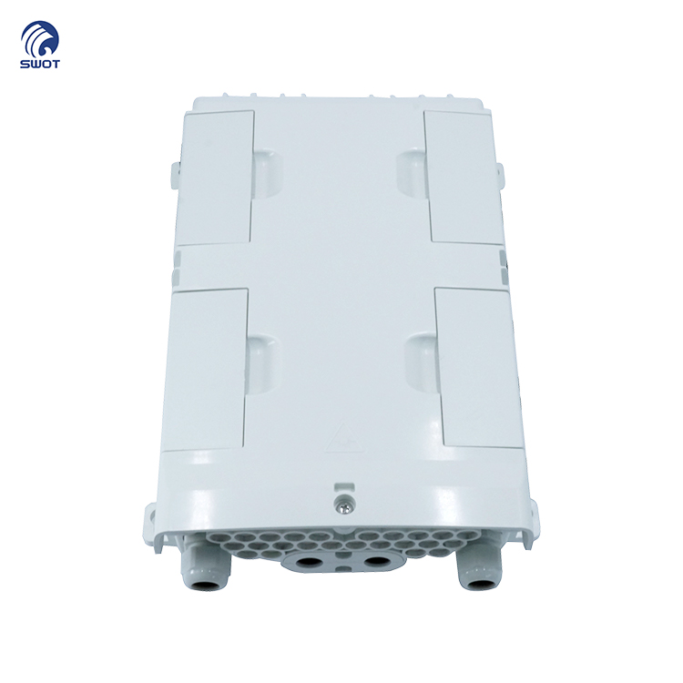
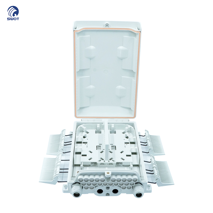
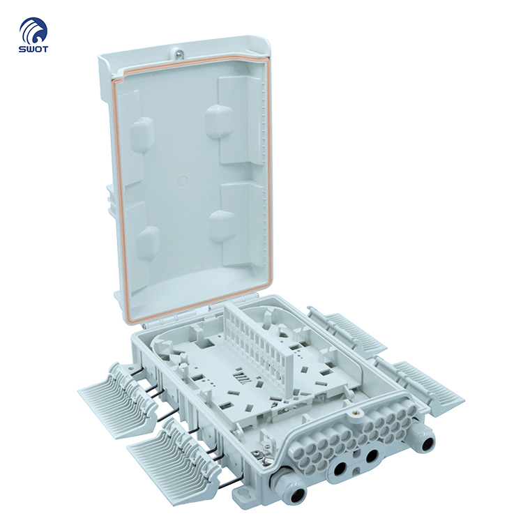

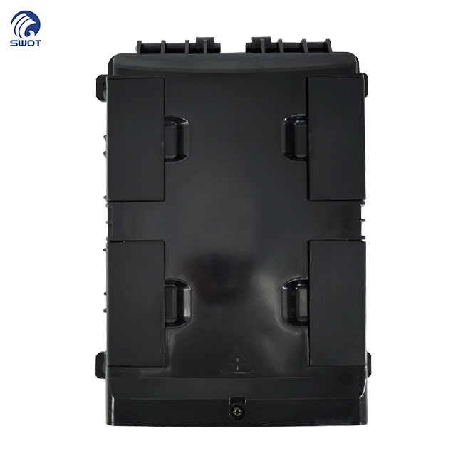
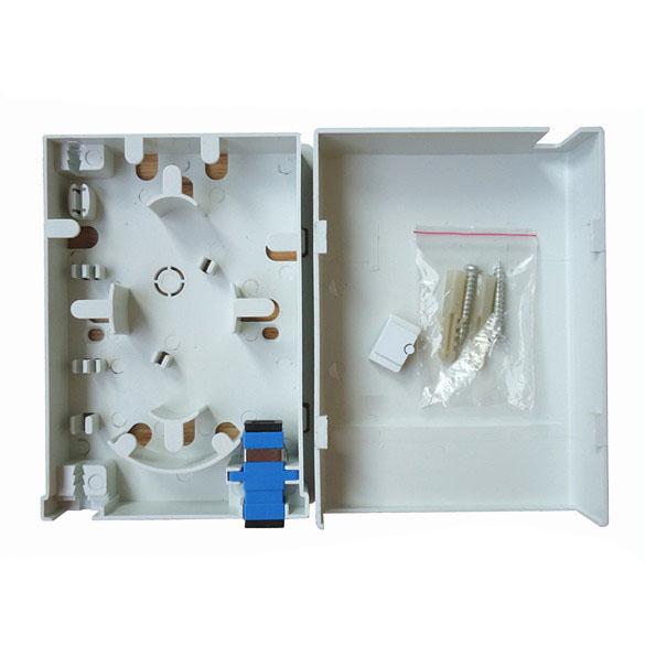
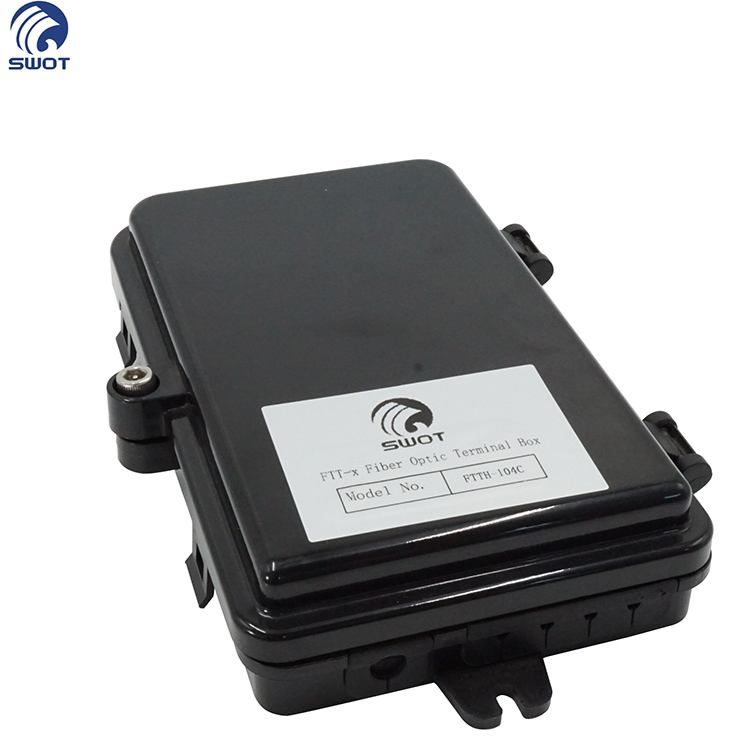
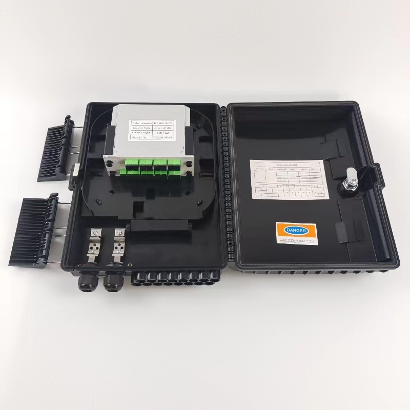
The equipment is used as a termination point for the feeder cable to connect with drop cable in FTTx communication network system. The fiber splicing, splitting, and distribution can be done in this box, and meanwhile it provides solid protection and management for the FTTx network building.
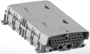
1. Total enclosed structure.
2. Material: PC+ABS, wet-proof, water-proof, dust-proof, anti-aging, protection level up to IP65.
3. Clamping for feeder cable and drop cable, fiber splicing, fixation, storage, distribution, etc., all in one.
4. Cable, pigtails, and patch cords are running through their own paths without disturbing each other, micro type PLC splitter installation, easy maintenance.
5. Distribution panel can be flipped up, feeder cable can be placed by expression port, easy for maintenance and installation.
6. Box can be installed by the way of wall-mounted or poled-mounted, suitable for both indoor and outdoor use.
1. Environmental requirement
Working temperature: -40℃~+85℃
Relative humidity: ≤85% (+30℃)
Atmospheric pressure: 70KPa~106Kpa
2. Main technical datasheet Insertion loss: ≤0. 15dB UPC return loss: ≥50dB
APC return loss: ≥60dB
3. Thunder-proof technical datasheet
The insulation resistance between the grounding device and the metal parts of the box is no less than 2, l04MΩ/500V (DC); IR≥2, l04 MΩ/500V.
The voltage resistance between the grounding device, and the box and its metal parts is no less than 3000V (DC)/min, no puncture, no flashover; U≥3000V
Table 1 Model and configuration
|
Model |
Size (Pic 1)A*B*C |
Max Capacity |
Derrick installation size(Pic 2)F*H |
Hang a wall to install size(Pic2)D*E |
Into the largest cable diameter (mm) |
|
FTT-H724 |
343*239*95 |
24 (SC/APC1/8PLC*3) |
221*265 |
61*274 |
13 |

Pic 1 Box Size
Pic 2 Installation Size
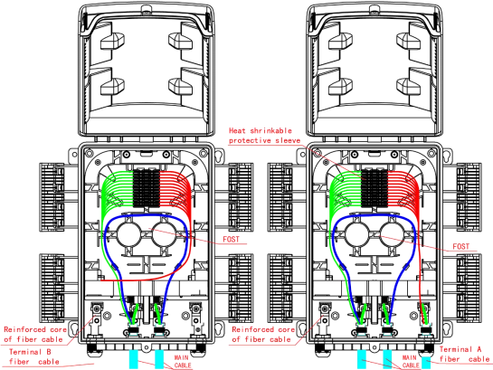
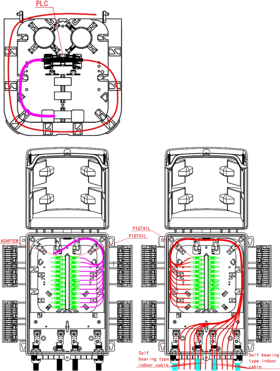
Pic.3 FTT-H724 Cable Ways
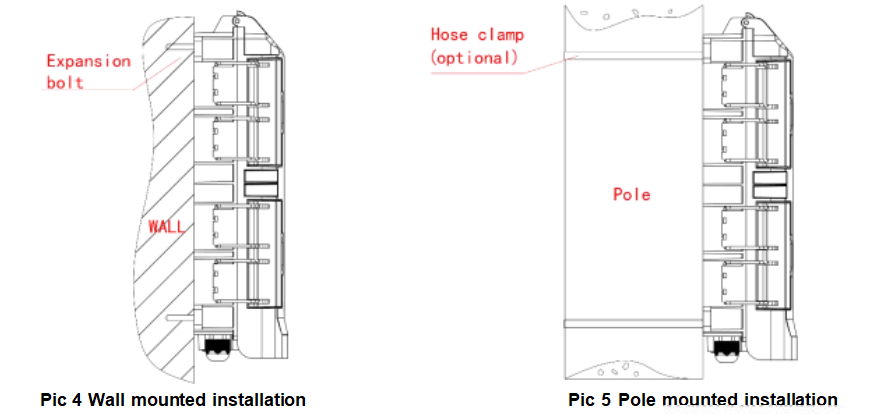
1. Wall-mounted installation
Drill 3 holes into the wall based on the size in table 1, place the expansion bolt Φ7.5*40, place the box to match up the holes and use bolt to fasten. (Pic 4)
2. Pole-mounted installation
Fix 1 set of the pole ring to the telecom pole (Pic 5)
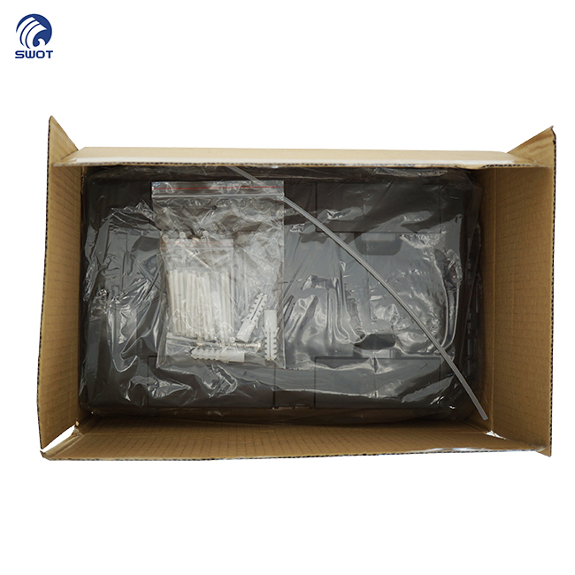
1. Users' Manual*1
2. Key*1
3. Accessories Bag*1
4. Pole Ring*2 (Option)

Copyright © 2026 Shanghai Wanbao Optical Technologies Co.,Ltd. All rights reserved. — Privacy Policy

 EN
EN