 ×
×

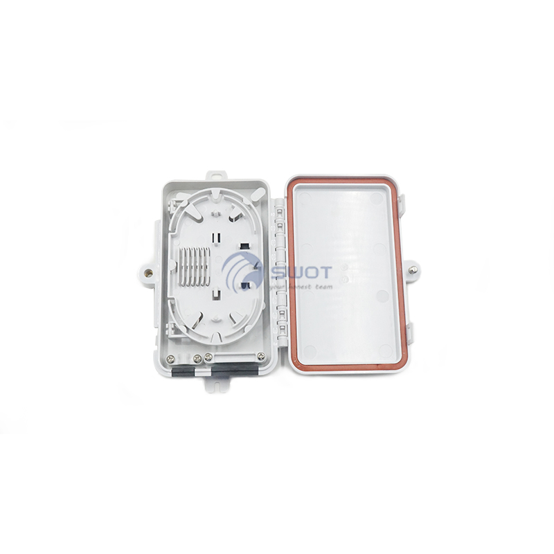
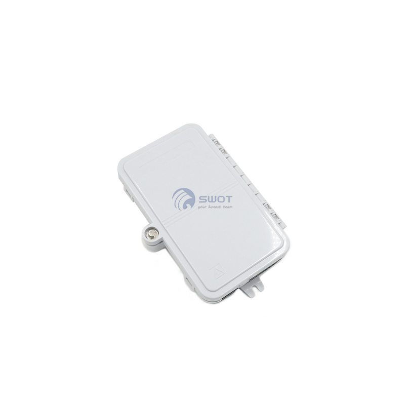
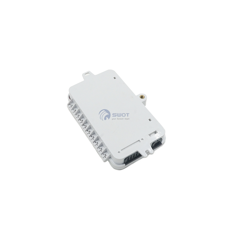
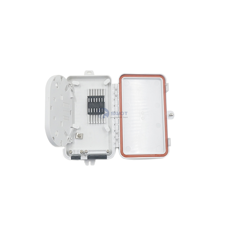
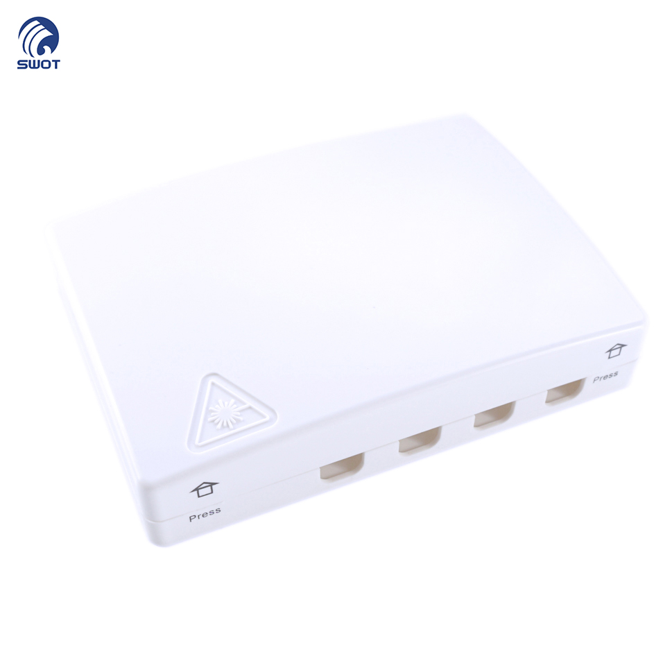
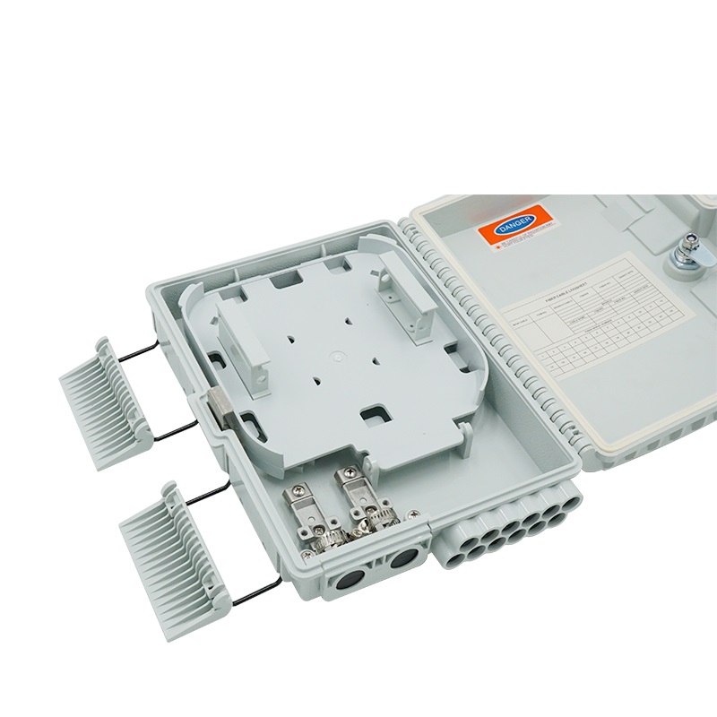
This product is suitable for the indoor cable's termination, fixing and fiber pigtail splicing in building and villas.

a, small size, light weight, beautiful appearance;
b, installed on the wall, with mechanical protection;
c, can achieve multiple fiber connections —direct splicing and splitting;
d, can effectively manage the fibers.
Fiber radius of curvature: ≥40mm
Optical disk additional loss: ≤ 0.01dB
Temperature Range: - 40 °C ~ + 70 °C
Anti lateral pressure: ≥2000N / 10 cm
Shock resistance: ≥20N.m
|
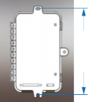
Size (mm): Lx W x H |
178*114*28 |
|
Weight(kg) |
0.14 |
|
Cable diameter (mm) |
Ø 3- Ø 10 |
|
Inlet / outlet |
1/12 |
|
Capacity |
12 (single core) |
|
Max spltting |
1:8 (1pc) |
1.Pre-install the box with the expansion screw in the desired position, mounting hole size: Ø5 (Figure 1)
2.Open the cover with a special key, strip the cable, remove the outer and inner sheath, loose tube, clean and remove the oil filling paste in the cable, leave 0.3~0.5m of bare fiber length, and fix it with the cable rack. The cable is pressed tightly at the same time; the bare fiber protective tube is used to protect the optical fiber, the optical fiber is coiled and the end is led to the splicing slot.
3.3a. Direct splice: After the cable is stripped and coiled in the box, the cable end is led to the heat-shrinkable tube which is pre-installed in the splicing slot, and is spliced with entry cable;
3b. Splitting: first, installed the adapter into the adapter slot, then insert the PLC splitter into the holder, introduce the inlet fiber to the splicing slot and splice with the incoming fiber; and insert the end pigtail into the adapter.
4. Tighten the cable pigtails by the pressing rack, lead the pigtails out through the sealing rubber provided at the outlet; finally, close the cover is closed, locked the box with a special key, and the installation is completed.
|
Closure main body |
1 set |
|
Heat shrinkable tube |
9 ~ 12 pcs (optional) |
|
Key |
1 pc |
|
M4 x 25 expansion screw |
2 sets |
|
Manual |
1 pc |

Copyright © 2026 Shanghai Wanbao Optical Technologies Co.,Ltd. All rights reserved. — Privacy Policy

 EN
EN